Getting Started
Hardware Required
• PICUNO Microcontroller board (built-in LED on GPIO 14).
• USB cable (for power and programming)
Circuit Diagram
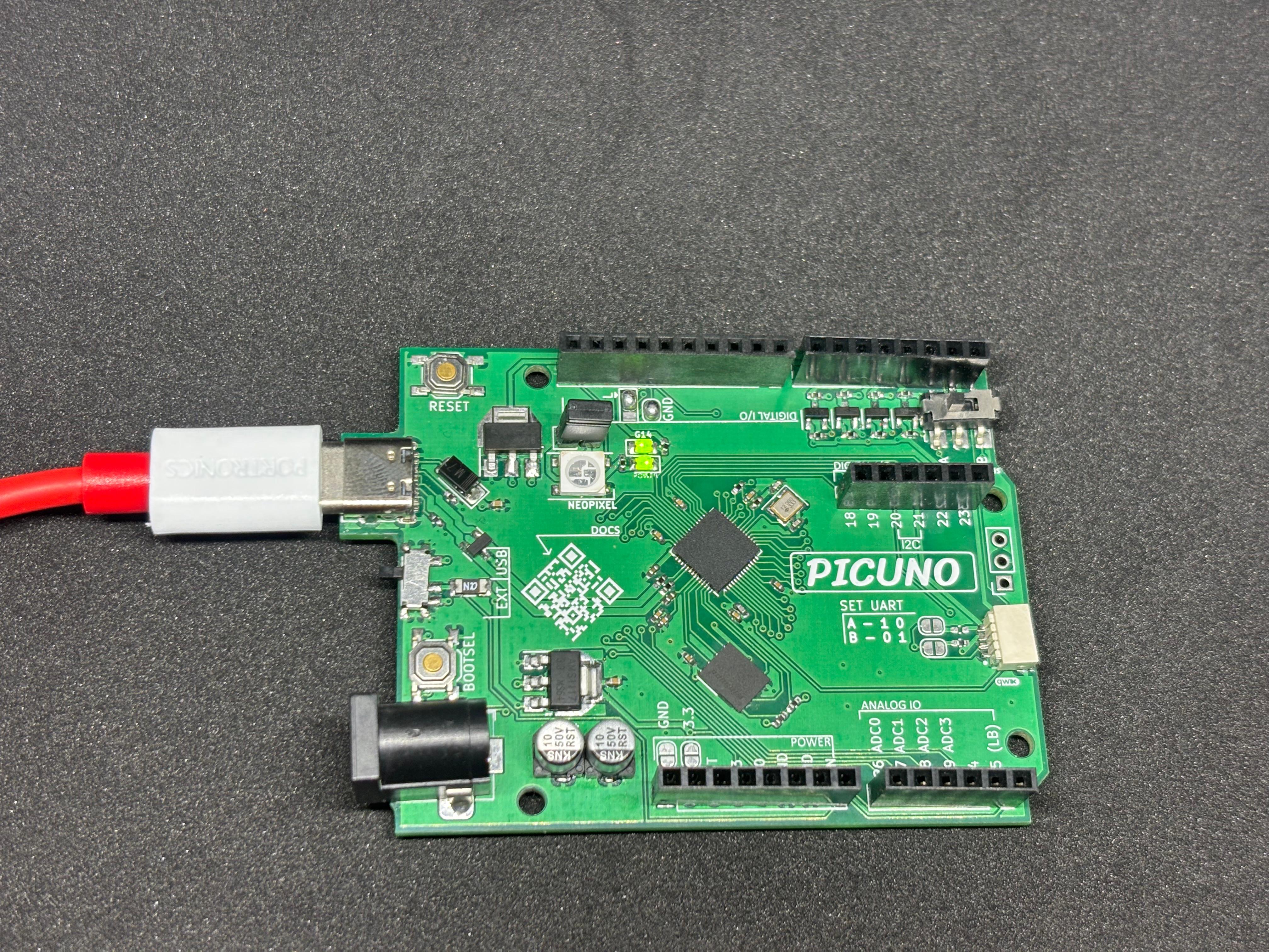
Circuit
Connect the PICUNO board to the computer using a USB cable.
No external wires or breadboard are required.
The built-in LED is already internally connected to GPIO 14 of the PICUNO board.
The code will configure GPIO 14 as an output and set it to HIGH, which turns the LED ON.
Schematic
This project uses the built-in LED on GPIO 14 of the PicUNO board. No additional circuit components are required.
Code - C
int ledPin = 14;
void setup() {
pinMode(14, OUTPUT);
digitalWrite(14, HIGH); // Turn ON the LED
}
void loop() {
// Nothing required here for continuous ON
}
void setup() {
pinMode(14, OUTPUT);
digitalWrite(14, HIGH); // Turn ON the LED
}
void loop() {
// Nothing required here for continuous ON
}
Let's break down the key functions used in this example:
pinMode(14, OUTPUT) - Sets GPIO 14 as an output pin.
digitalWrite(14, HIGH) - Sends a HIGH signal to the pin to power the LED.
pinMode(14, OUTPUT) - Sets GPIO 14 as an output pin.
digitalWrite(14, HIGH) - Sends a HIGH signal to the pin to power the LED.
Code - MicroPython
from machine import Pin
# Setup built-in LED
led = Pin(14, Pin.OUT)
led.value(1) # Turn ON the LED
# Setup built-in LED
led = Pin(14, Pin.OUT)
led.value(1) # Turn ON the LED
Pin(14, Pin.OUT) - Sets GPIO 14 as an output pin.
led.value(1) - Sends a HIGH signal to the pin to power the LED.