LED Blink using built-in LED
HARDWARE REQUIRED:
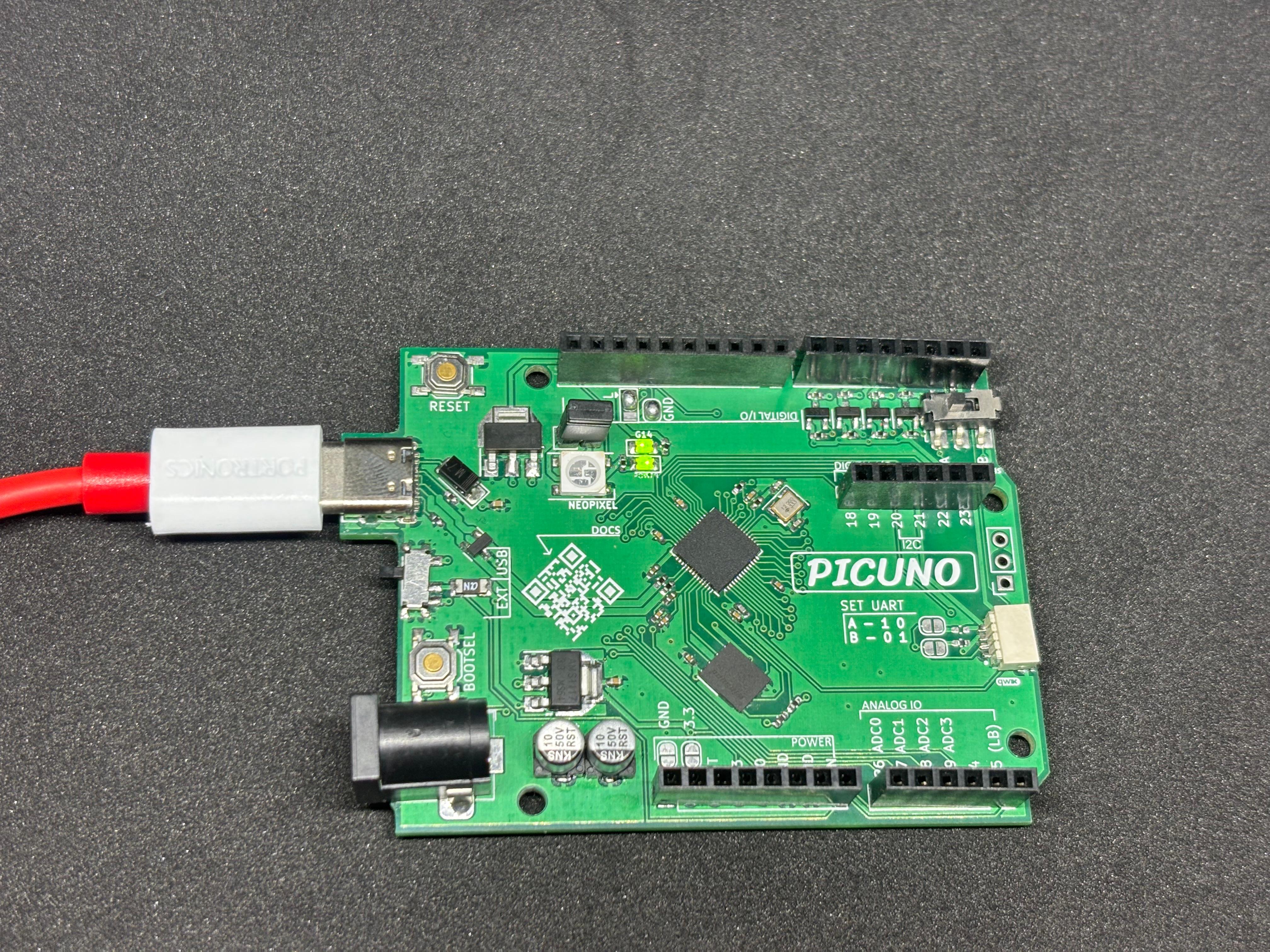
- PICUNO Microcontroller board (built-in LED on GPIO 14)
- USB cable (for power and programming)
Description
The LED is controlled using digital output on GPIO 14. In the first method, it turns ON and OFF every 1 second using a blocking delay. In the second method, the code checks elapsed time using a timer and toggles the LED without stopping the program, which is useful for multitasking.
Circuit Diagram
Circuit
- Connect the PICUNO board to the computer using a USB cable.
- No external wires or breadboard are required.
- The built-in LED is already internally connected to GPIO 14 of the PICUNO board.
- The code simply sets GPIO 14 as output and toggles it in a loop to create the blink effect.
Schematic
This project uses the built-in LED on GPIO 14 of the PicUNO board. No additional circuit components are required.
Code - C
int ledPin = 14;
void setup() {
pinMode(ledPin, OUTPUT);
}
void loop() {
digitalWrite(ledPin, HIGH);
delay(1000);
digitalWrite(ledPin, LOW);
delay(1000);
}
void setup() {
pinMode(ledPin, OUTPUT);
}
void loop() {
digitalWrite(ledPin, HIGH);
delay(1000);
digitalWrite(ledPin, LOW);
delay(1000);
}
pinMode(14, OUTPUT) - Sets GPIO 14 as an output pin.
digitalWrite() - Sets the LED state.
delay() - Introduce a fixed blocking pause.
digitalWrite() - Sets the LED state.
delay() - Introduce a fixed blocking pause.
Micropython
from machine import Pin
import time
led = Pin(14, Pin.OUT)
while True:
led.toggle()
time.sleep(1)
import time
led = Pin(14, Pin.OUT)
while True:
led.toggle()
time.sleep(1)
Pin(14, Pin.OUT) - Sets GPIO 14 as an output pin.
time.sleep() - Introduce a fixed blocking pause.
led.toggle() - Toggle the current state of the LED.
time.sleep() - Introduce a fixed blocking pause.
led.toggle() - Toggle the current state of the LED.