External LED blink control with breadboard circuit
Hardware Required
- PICUNO Microcontroller board
- 1× LED
- 1× 220Ω resistor
- Breadboard
- Jumper wires
- USB cable
Description
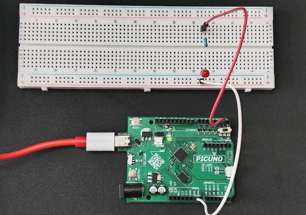
This project demonstrates how to blink an external LED connected on a breadboard using the PICUNO board. The LED is connected in series with a resistor to GPIO pin 2. When the GPIO is set to HIGH, current flows through the LED and it lights up. When it is set to LOW, the LED turns off. This causes the LED to blink either using a blocking delay or a non-blocking timer logic.
Circuit Diagram
[Fritzing image to be added here]
Circuit
- Connect the PICUNO board to the computer using a USB cable.
- Insert the LED on the breadboard.
- Connect the longer leg (anode) of the LED to one terminal of a 220Ω resistor.
- Connect the other terminal of the resistor to GPIO pin 2 on the PicUNO using a jumper wire.
- Connect the shorter leg (cathode) of the LED to GND on the PicUNO board.
Schematic
GPIO 2 → 220Ω Resistor → LED Anode
LED Cathode → GND
Code - C
#define LED_PIN 2
void setup() {
pinMode(LED_PIN, OUTPUT);
}
void loop() {
digitalWrite(LED_PIN, HIGH); // LED ON
delay(1000);
digitalWrite(LED_PIN, LOW); // LED OFF
delay(1000);
}
void setup() {
pinMode(LED_PIN, OUTPUT);
}
void loop() {
digitalWrite(LED_PIN, HIGH); // LED ON
delay(1000);
digitalWrite(LED_PIN, LOW); // LED OFF
delay(1000);
}
pinMode(LED_PIN, OUTPUT) - Sets GPIO pin 2 as an output pin.
digitalWrite(HIGH/LOW) - Controls LED ON and OFF states.
delay(1000) - Introduces blocking delay for blink timing.
digitalWrite(HIGH/LOW) - Controls LED ON and OFF states.
delay(1000) - Introduces blocking delay for blink timing.
Code - Micropython
from machine import Pin
import time
led = Pin(2, Pin.OUT)
while True:
led.value(1) # LED ON
time.sleep(1)
led.value(0) # LED OFF
time.sleep(1)
import time
led = Pin(2, Pin.OUT)
while True:
led.value(1) # LED ON
time.sleep(1)
led.value(0) # LED OFF
time.sleep(1)
Pin(2, Pin.OUT) - Configures GPIO 2 as output to control the LED.
led.value(1) / led.value(0) - Turns LED ON and OFF by sending HIGH and LOW signals.
led.value(1) / led.value(0) - Turns LED ON and OFF by sending HIGH and LOW signals.