Traffic light system simulation with three LEDs
Hardware Required
- PICUNO Microcontroller board
- 3 × LEDs (Red, Yellow, Green)
- 3 × 220Ω resistors
- Breadboard
- Jumper wires
- USB cable
Description
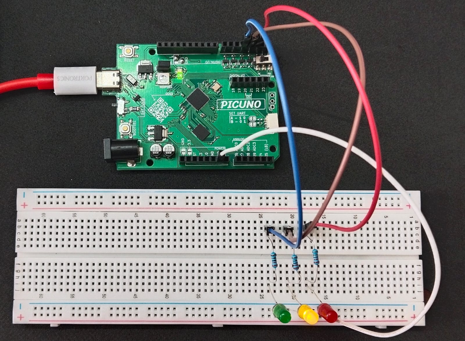
This project simulates a basic traffic light system using three LEDs to represent the red, yellow, and green signals. The lights switch in a predefined timing sequence: Red → Green → Yellow → Red, mimicking real-world traffic signals.
Circuit Diagram
[Fritzing image to be added here]
Circuit
- Connect the PICUNO board to the computer using a USB cable.
- Connect the red LED anode to one end of a 220Ω resistor, and the other end to GPIO 2.
- Connect the yellow LED anode to a 220Ω resistor, and the other end to GPIO 3.
- Connect the green LED anode to a 220Ω resistor, and the other end to GPIO 4.
- Connect all LED cathodes to GND.
Schematic
GPIO 2 → 220Ω → Red LED Anode
GPIO 3 → 220Ω → Yellow LED Anode
GPIO 4 → 220Ω → Green LED Anode
All LEDs Cathode → GND
Code - C
#define RED 2
#define YELLOW 3
#define GREEN 4
void setup() {
pinMode(RED, OUTPUT);
pinMode(YELLOW, OUTPUT);
pinMode(GREEN, OUTPUT);
}
void loop() {
digitalWrite(RED, HIGH);
digitalWrite(YELLOW, LOW);
digitalWrite(GREEN, LOW);
delay(5000);
digitalWrite(RED, LOW);
digitalWrite(GREEN, HIGH);
delay(5000);
digitalWrite(GREEN, LOW);
digitalWrite(YELLOW, HIGH);
delay(3000);
digitalWrite(YELLOW, LOW);
}
pinMode(pin, OUTPUT) - Sets each GPIO as output.
digitalWrite(pin, HIGH/LOW) - Turns each light ON or OFF.
delay(ms) - Waits for the specified duration in milliseconds.
digitalWrite(pin, HIGH/LOW) - Turns each light ON or OFF.
delay(ms) - Waits for the specified duration in milliseconds.
Code - Micropython
from machine import Pin
import time
red = Pin(2, Pin.OUT)
yellow = Pin(3, Pin.OUT)
green = Pin(4, Pin.OUT)
while True:
red.value(1)
yellow.value(0)
green.value(0)
time.sleep(5)
red.value(0)
green.value(1)
time.sleep(5)
green.value(0)
yellow.value(1)
time.sleep(3)
yellow.value(0)
import time
red = Pin(2, Pin.OUT)
yellow = Pin(3, Pin.OUT)
green = Pin(4, Pin.OUT)
while True:
red.value(1)
yellow.value(0)
green.value(0)
time.sleep(5)
red.value(0)
green.value(1)
time.sleep(5)
green.value(0)
yellow.value(1)
time.sleep(3)
yellow.value(0)
Pin(x, Pin.OUT) - Initializes GPIO pins for red, yellow, and green LEDs.
.value(1/0) - Turns each LED ON or OFF.
time.sleep(seconds) - Adds delays to simulate real traffic light timing.
.value(1/0) - Turns each LED ON or OFF.
time.sleep(seconds) - Adds delays to simulate real traffic light timing.