Tilt sensor alarm system
HARDWARE REQUIRED:
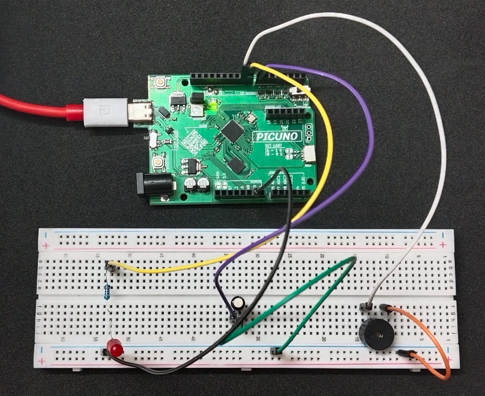
- PICUNO Microcontroller board
- 1 × LED
- 1 × 220Ω resistor
- 1 × SW-520D Tilt Sensor
- 1 × Buzzer
- Breadboard
- Jumper wires
- USB cable
DESCRIPTION:
This project uses the internal pull-up resistor on the PicUNO input pin to detect tilt using a SW-520D sensor. When still, the input reads HIGH. When tilted, the sensor contacts close and pull the pin LOW. When motion is detected, both LED and buzzer are turned ON. The alert turns OFF when the sensor is stable again.
CIRCUIT DIAGRAM:
[Fritzing image to be added here]
- Connect the PICUNO board to the computer using a USB cable.
- Connect the one leg of the tilt sensor to GPIO 7.
- Connect the other leg of the tilt sensor to GND.
- Connect the anode (the longer leg) of the LED to GPIO 8 through 220Ω resistor.
- Connect the cathode (the shorter leg) of the LED to GND.
- Connect the positive side of the buzzer to GPIO 9.
- Connect the negative side of the buzzer to GND.
SCHEMATIC:
One tilt sensor pin → GND
Other tilt sensor pin → GPIO 7 (internal pull-up)
LED anode → 220-ohm resistor → GPIO 8
LED cathode → GND
Buzzer +ve → GPIO 9
Buzzer -ve → GND
CODE -- C:
#define TILT_PIN 7
#define LED_PIN 8
#define BUZZER_PIN 9
void setup() {
pinMode(TILT_PIN, INPUT_PULLUP); // Internal pull-up
pinMode(LED_PIN, OUTPUT);
pinMode(BUZZER_PIN, OUTPUT);
}
void loop() {
int tilt = digitalRead(TILT_PIN);
if (tilt == HIGH) {
digitalWrite(LED_PIN, HIGH);
digitalWrite(BUZZER_PIN, HIGH);
} else {
digitalWrite(LED_PIN, LOW);
digitalWrite(BUZZER_PIN, LOW);
}
delay(100); // Debounce delay
}
digitalRead(TILT_PIN) - Reads HIGH when sensor is open (no tilt), LOW when tilted.
digitalWrite(...) - Activates or deactivates the LED and buzzer based on sensor reading.
delay(100) - Adds a debounce delay to prevent flickering.
digitalWrite(...) - Activates or deactivates the LED and buzzer based on sensor reading.
delay(100) - Adds a debounce delay to prevent flickering.
CODE -- PYTHON:
from machine import Pin
import time
sensor = Pin(7, Pin.IN, Pin.PULL_UP) # SW-520D digital output
buzzer = Pin(9, Pin.OUT) # Active Buzzer
led = Pin(8, Pin.OUT)
while True:
if sensor.value() == 1:
print(\"⚠️ Movement Detected! ALARM ON\")
buzzer.value(1)
led.value(1)
else:
buzzer.value(0)
led.value(0)
time.sleep(0.1)
import time
sensor = Pin(7, Pin.IN, Pin.PULL_UP) # SW-520D digital output
buzzer = Pin(9, Pin.OUT) # Active Buzzer
led = Pin(8, Pin.OUT)
while True:
if sensor.value() == 1:
print(\"⚠️ Movement Detected! ALARM ON\")
buzzer.value(1)
led.value(1)
else:
buzzer.value(0)
led.value(0)
time.sleep(0.1)
sensor.value() == 1 - Detects when the sensor is open (indicating motion in this logic).
buzzer.value(1) / led.value(1) - Activates buzzer and LED when motion is detected.
time.sleep(0.1) - Adds a short delay to stabilize the loop and debounce minor fluctuations
buzzer.value(1) / led.value(1) - Activates buzzer and LED when motion is detected.
time.sleep(0.1) - Adds a short delay to stabilize the loop and debounce minor fluctuations