PUSH BUTTON INPUT : PULL-DOWN LOGIC
Hardware Required
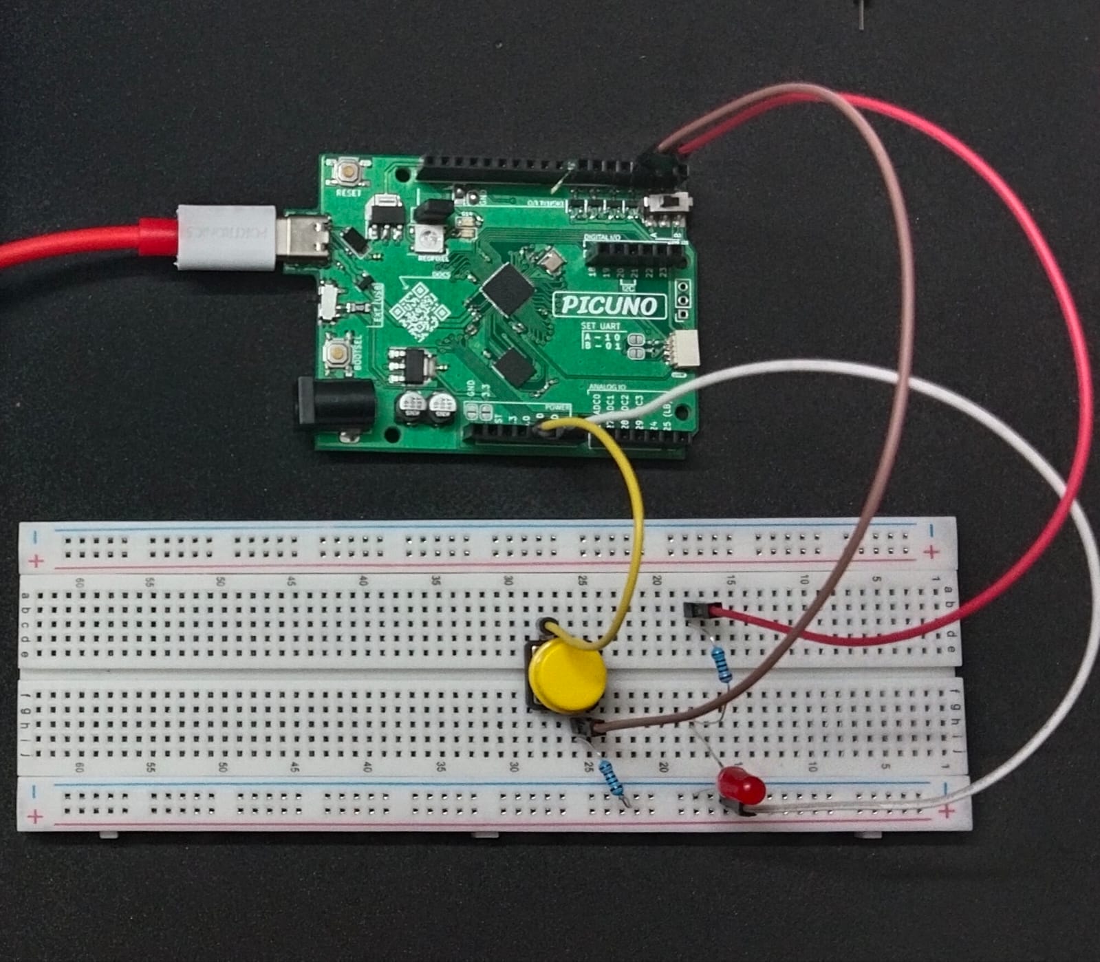
- PICUNO Microcontroller board
- 1 × LED
- 1 × 220Ω resistor
- 1 × Push Button (4-pin or 2-pin)
- 1 × 10kΩ resistor
- Breadboard
- Jumper wires
- USB cable
Description
This project demonstrates pull-down logic. When the button is pressed, the pin reads LOW and the LED turns ON.
Circuit Diagram
[Fritzing image to be added here]
Circuit
- Connect the PICUNO board to the computer using a USB cable.
- Connect the anode (longer leg) of the LED to GPIO 2 through a 220Ω resistor.
- Connect the cathode (short leg) of the LED to GND.
- Connect one leg of the push button to 3.3V.
- Connect the other leg of the button to GPIO 3.
- Connect one end of the 10kΩ resistor to GPIO 3 and other end to GND.
Schematic
Button one side → 3.3V
Other side → GPIO 3
GPIO 3 → 10kΩ → GND
GPIO 2 → 220Ω → LED anode
LED cathode → GND
Code - C
#define LED_PIN 2
#define BUTTON_PIN 3
void setup() {
pinMode(LED_PIN, OUTPUT);
pinMode(BUTTON_PIN, INPUT);
}
void loop() {
if (digitalRead(BUTTON_PIN) == HIGH) {
digitalWrite(LED_PIN, HIGH);
} else {
digitalWrite(LED_PIN, LOW);
}
delay(10);
}
#define BUTTON_PIN 3
void setup() {
pinMode(LED_PIN, OUTPUT);
pinMode(BUTTON_PIN, INPUT);
}
void loop() {
if (digitalRead(BUTTON_PIN) == HIGH) {
digitalWrite(LED_PIN, HIGH);
} else {
digitalWrite(LED_PIN, LOW);
}
delay(10);
}
digitalRead(BUTTON_PIN) == LOW - Detects button press.
digitalWrite(LED_PIN, HIGH/LOW) - Controls LED based on button state.
digitalWrite(LED_PIN, HIGH/LOW) - Controls LED based on button state.
Code - Micropython
from machine import Pin
import time
led = Pin(2, Pin.OUT)
button = Pin(3, Pin.IN)
while True:
if button.value() == 1:
led.value(1)
else:
led.value(0)
time.sleep(0.01)
import time
led = Pin(2, Pin.OUT)
button = Pin(3, Pin.IN)
while True:
if button.value() == 1:
led.value(1)
else:
led.value(0)
time.sleep(0.01)
button.value() == 0 - Detects when button is pressed (LOW).
led.value(1) / value(0) - Turns LED ON or OFF.
led.value(1) / value(0) - Turns LED ON or OFF.