Light Gesture Recognizer With TinyML
DESCRIPTION:
TECHNOLOGY STACK:
ML Platform: Edge Impulse (a TinyML platform for data collection, training, and deployment).
Development Environment: Arduino® IDE (for C++ programming and deployment to the board).
Connectivity: Edge Impulse CLI for bridging the hardware with the cloud platform.
HARDWARE REQUIRED:
- PICUNO Microcontroller board
- 1 × HW-486 Light Dependent Resistor (LDR) module
- Jumper wires
- USB cable
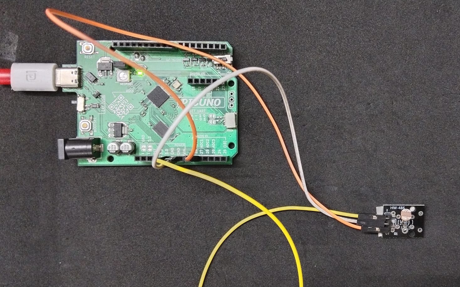
CIRCUIT DIAGRAM:
LDR MODULE:
- Connect the VCC / + pin to 5V pin on the board.
- Connect the GND / - pin to GND pin on board.
- Connect the Signal / S pin to Analog Pin A0 (GPIO 26).
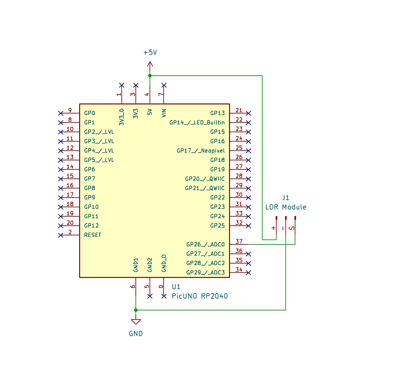
SCHEMATIC:
LDR VCC / (+) → 5V
LDR GND / (-) → GND
LDR Signal / (S) → A0 (GPIO 26)
ENVIRONMENT AND SOFTWARE SETUP:
1. Flash PicUNO Firmware:
- Download the special Edge Impulse firmware for the RP2040 from https://cdn.edgeimpulse.com/firmware/raspberry-rp2040.zip
- Put the Picuno into bootloader mode: hold down the BOOTSEL button, plug it into your computer, then release the button. It will appear as a USB drive.
- Drag and drop the downloaded firmware file (.uf2) onto that drive. The board will automatically reboot.
2. Node.js Installation:
- Install Node.js LTS version from the official website: https://nodejs.org. Run the installer, accepting all the default options.
- After it's installed, close and open the Command Prompt and type these commands one after the other: node -v and npm -v.
- You could see the version numbers (e.g., v18.17.0), that denotes the Node.js (LTS version) was installed, which provides the npm package manager.
3. Build Tools Installation:
- Install Build Tools for Visual Studio (https://visualstudio.microsoft.com/downloads/) with the "Desktop development with C++" workload.
- Install Python (https://www.python.org/downloads/) and ensure it was added to the system PATH.
- After the installation is complete, restart your computer to ensure all system paths and environment variables are updated correctly.
4. Final Installation:
- After restarting, open a new Command Prompt as Administrator and run the installation command:
- npm install -g edge-impulse-cli
5. Setting up Edge Impulse:
- Create an Account: Go to edgeimpulse.com and sign up for a free account. Once you're in, create a new project and give it a name "Light Gesture Recognizer."
- Set a Password in Edge Impulse Studio: Once you are on your project dashboard, look at the menu on the right side. Click on "Account settings". You will see a section to "Set password". Create a new password for your account and save it.
- Connect the PicUNO to Edge Impulse: Ensure the Picuno board is running the Edge Impulse firmware. Open a new Command Prompt (it does not need to be an administrator prompt). Run the daemon command: edge-impulse-daemon --clean
- Follow the on-screen prompts to log in to your account and select your project. And the given link when selected will redirect you to Edge Impulse Studio. Your Picuno should now appear as a connected device in your Edge Impulse Studio under the Devices tab.
ML DEVELOPMENT MODEL WORKFLOW (EDGE IMPULSE):
1. Data Collection:
- Go to the Data acquisition tab in your Edge Impulse project.
- In the "Collect data" box on the right:
- Device: Select picuno.
- Label: Type the name of the gesture you are about to perform.
- Sample length: Set to 2000 (2 seconds).
- Sensor: Select "ADC sensor". This will record data from all available analog pins, including the A0 you've connected.
- Collect gesture samples (20-30 of each):
- Ambient: The normal, steady light in the room.
- Cover: Covering the LDR with a hand or placing it in a dark space.
- Blink: Pulsing a flashlight on and off over the sensor.
2. Impulse Design:
- A pipeline was designed to process the time-series data from the LDR:
- Create Impulse: Go to "Create impulse".
- Input block: Time series data.
- Processing block: Spectral Analysis.
- Learning block: Classification (Keras).
- Click Save Impulse.
- Processing Block: Go to the "Spectral features" tab and click Generate features. Spectral Analysis was chosen to extract key features (like frequency and power) from the motion data.
- Learning Block: Go to the "Classifier" tab and click Start training. A Classification (Keras) block was used to create a neural network to learn the patterns from the extracted features.
3. Model Training:
After generating features, the neural network was trained. The model achieved 100% accuracy on the validation set, demonstrating a perfect ability to distinguish between the three distinct light patterns.
4. Testing the Model:
- On the left menu, go to the "Live classification" tab.
- Your picuno device should be connected. Click "Start sampling" and perform one of your gestures.
- The model will analyze the movement in real-time and show you its prediction.
DEPLOYMENT TO PICUNO:
1. Deploy Model:
Go to the "Deployment" tab, select "Arduino® library", and click Build. This will generate a .zip file containing the complete, optimized model and all necessary functions.
2. Arduino® Setup:
- Open a New Sketch in Arduino® IDE.
- Go to Sketch → Include Library → Add .zip library… and select the downloaded .zip file.
- You can find the added library file in File → Examples → Light_gesture_Recognizer_inferencing
FINAL CODE:
Code Explanation:
#include <Light_gesture_Recognizer_inferencing.h> - Includes the machine learning model library generated by Edge Impulse.
FREQUENCY_HZ = 100 - Samples the LDR sensor 100 times per second to match the training data frequency.
buffer[ix] = (float)analogRead(A0) - Reads the analog value from the LDR sensor and stores it in the buffer for classification.
run_classifier(&signal, &result, debug_nn) - Runs the trained neural network model on the collected sensor data and stores predictions in the result structure.
result.classification[i].value - Contains the confidence score (0.0 to 1.0) for each gesture class (ambient, cover, blink).
RESULTS:
By opening the Arduino® Serial Monitor at 115200 baud, the live classification results were successfully displayed, with the board accurately predicting the performed gestures.
CONCLUSION:
This project successfully demonstrated that the PicUNO board is fully capable of running a modern, real-time machine learning model. The use of the Edge Impulse platform streamlined the development process, from data collection to deployment. The final system accurately classifies light gestures, proving the viability of the hardware for TinyML applications.