Display Numbers On 5161as Single-Digit 7 Segment Display
Hardware Required
- PICUNO Microcontroller board
- 5161AS Single-Digit 7-Segment Display (Common Cathode)
- Breadboard
- Jumper wires
- USB cable
Description
The 5161AS is a single-digit 7-segment display. Each segment (A to G and DP) is individually controlled. The display is common cathode, meaning cathode pins (COM1 or COM2) should be connected to ground. The PicUNO will display digits from 0 to 9 one by one with a short delay. This is done by setting the appropriate HIGH/LOW values on the GPIO pins connected to each segment based on a digit's pattern.
Circuit Diagram
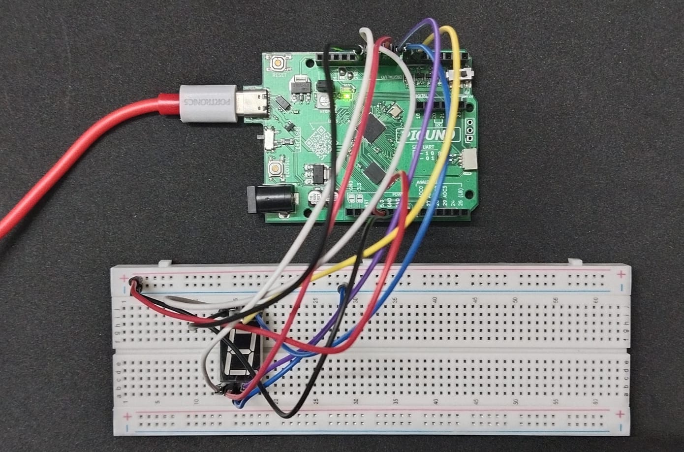
Circuit
- Connect the PICUNO board to the computer using a USB cable.
- Connect segment pins A to G to GPIO pins 6 to 12 on the PicUNO.
- Connect either COM1 or COM2 (or both) to GND.
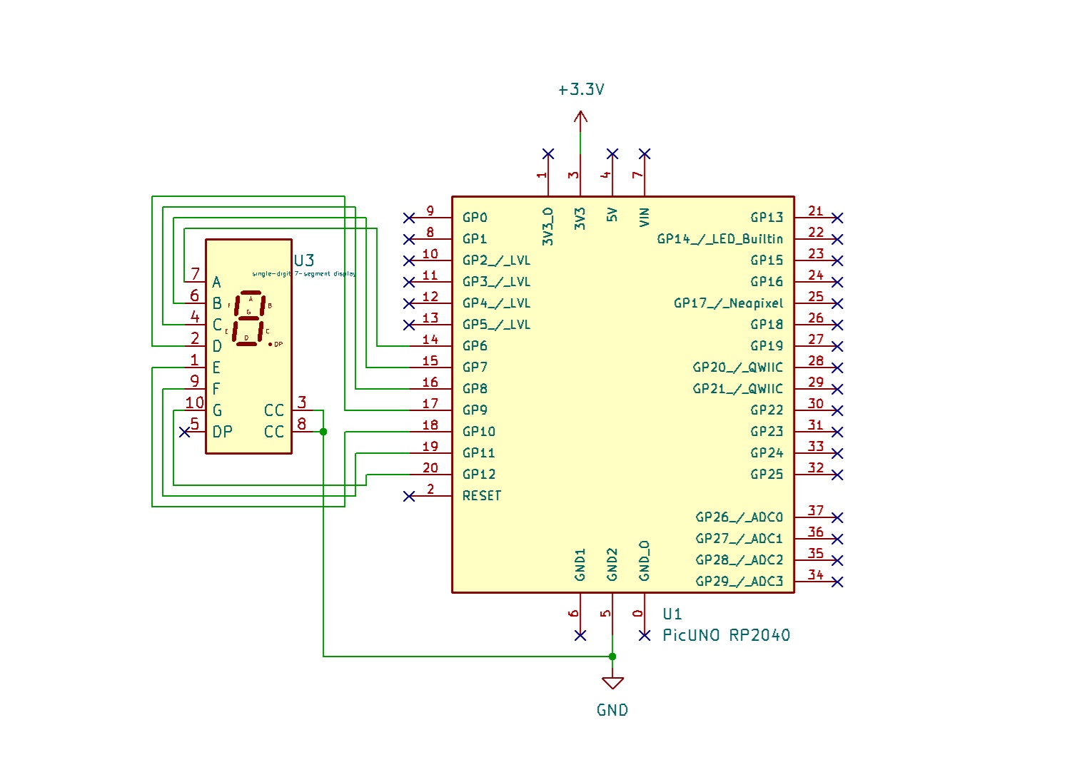
Schematic
A → GPIO 6
B → GPIO 7
C → GPIO 8
D → GPIO 9
E → GPIO 10
F → GPIO 11
G → GPIO 12
COM 1 or COM 2 → GND
Code - C
int segmentPins[7] = {6, 7, 8, 9, 10, 11, 12};
byte digits[10][7] = {
{1,1,1,1,1,1,0}, // 0
{0,1,1,0,0,0,0}, // 1
{1,1,0,1,1,0,1}, // 2
{1,1,1,1,0,0,1}, // 3
{0,1,1,0,0,1,1}, // 4
{1,0,1,1,0,1,1}, // 5
{1,0,1,1,1,1,1}, // 6
{1,1,1,0,0,0,0}, // 7
{1,1,1,1,1,1,1}, // 8
{1,1,1,1,0,1,1} // 9
};
void setup() {
for (int i = 0; i < 7; i++) {
pinMode(segmentPins[i], OUTPUT);
}
}
void loop() {
for (int d = 0; d < 10; d++) {
for (int i = 0; i < 7; i++) {
digitalWrite(segmentPins[i], digits[d][i]);
}
delay(1000);
}
}
segmentPins[] - stores the GPIO pins used for the 7 segments (A to G).
digits[][] - contains segment ON/OFF patterns for each digit from 0 to 9.
In setup(), all segment pins are set as output.
In loop(), it iterates over digits 0–9, writing the correct pattern to each segment and delaying for 1 second.
digits[][] - contains segment ON/OFF patterns for each digit from 0 to 9.
In setup(), all segment pins are set as output.
In loop(), it iterates over digits 0–9, writing the correct pattern to each segment and delaying for 1 second.
Code - Micropython
from machine import Pin
import time
segments = [Pin(i, Pin.OUT) for i in range(6, 13)] # GPIO 6-12 for A-G
# Segment bitmaps for digits 0-9 (ABCDEFG)
numbers = [
[1,1,1,1,1,1,0], # 0
[0,1,1,0,0,0,0], # 1
[1,1,0,1,1,0,1], # 2
[1,1,1,1,0,0,1], # 3
[0,1,1,0,0,1,1], # 4
[1,0,1,1,0,1,1], # 5
[1,0,1,1,1,1,1], # 6
[1,1,1,0,0,0,0], # 7
[1,1,1,1,1,1,1], # 8
[1,1,1,1,0,1,1] # 9
]
while True:
for digit in range(10):
for i in range(7):
segments[i].value(numbers[digit][i])
time.sleep(1)
segments[] - creates a list of Pin objects from GPIO 6 to 12.
numbers[] - holds the segment patterns for displaying digits 0 to 9.
for digit in range(10) - loops through each number.
segments[i].value() - sends the pattern to the GPIO pins.
time.sleep(1) - adds a 1-second delay between digits.
numbers[] - holds the segment patterns for displaying digits 0 to 9.
for digit in range(10) - loops through each number.
segments[i].value() - sends the pattern to the GPIO pins.
time.sleep(1) - adds a 1-second delay between digits.