Button controlled LED with push button input
Hardware Required
- PICUNO Microcontroller board
- 1 × LED
- 1 × 220Ω resistor
- 1 × Push Button (4-pin or 2-pin)
- Breadboard
- Jumper wires
- USB cable
Description
The button is set up so that when not pressed, GPIO 3 reads HIGH (internal pull-up). When pressed, the pin reads LOW. The program checks the button state and turns the LED ON only when the button is pressed and held down.
Circuit Diagram
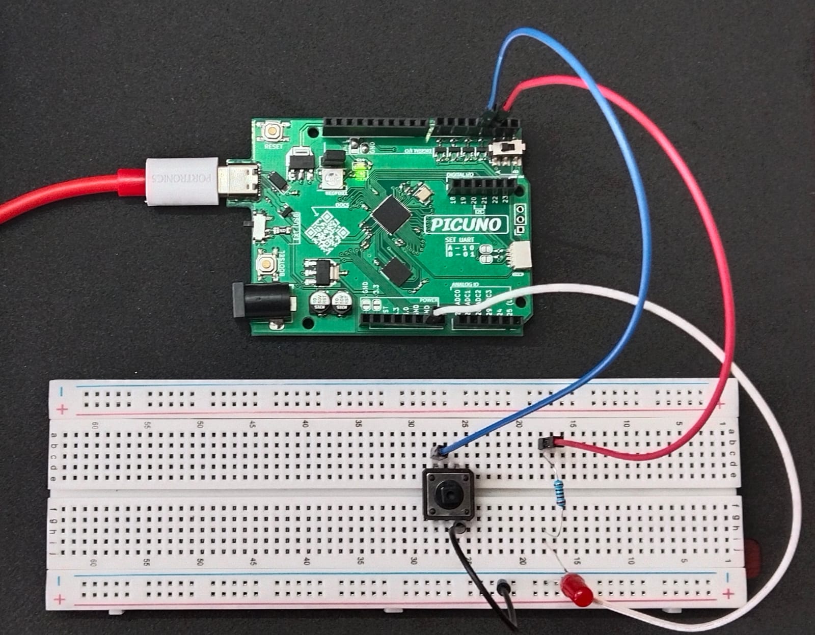
Circuit
- Connect the PICUNO board to the computer using a USB cable.
- Connect the anode (longer leg) of the LED to GPIO 2 through a 220Ω resistor.
- Connect the cathode (short leg) of the LED to GND.
- Connect one leg of the push button to GPIO 3.
- Connect the other leg of the button to GND.
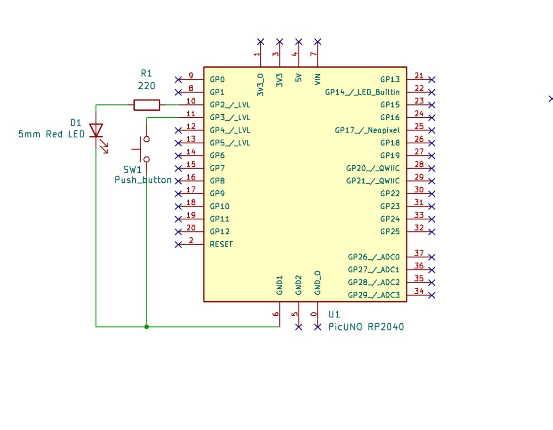
Schematic
GPIO 2 → 220Ω → LED Anode
LED Cathode → GND
GPIO 3 ← Push Button → GND
Code - C
#define LED_PIN 2
#define BUTTON_PIN 3
void setup() {
pinMode(LED_PIN, OUTPUT);
pinMode(BUTTON_PIN, INPUT_PULLUP); // Active LOW
}
void loop() {
if (digitalRead(BUTTON_PIN) == LOW) {
digitalWrite(LED_PIN, HIGH);
} else {
digitalWrite(LED_PIN, LOW);
}
delay(10); // Small delay for stability
}
#define BUTTON_PIN 3
void setup() {
pinMode(LED_PIN, OUTPUT);
pinMode(BUTTON_PIN, INPUT_PULLUP); // Active LOW
}
void loop() {
if (digitalRead(BUTTON_PIN) == LOW) {
digitalWrite(LED_PIN, HIGH);
} else {
digitalWrite(LED_PIN, LOW);
}
delay(10); // Small delay for stability
}
INPUT_PULLUP - Uses internal pull-up resistor.
digitalRead(BUTTON_PIN) == LOW - Detects button press.
digitalWrite(LED_PIN, HIGH/LOW) - Controls LED based on button state.
digitalRead(BUTTON_PIN) == LOW - Detects button press.
digitalWrite(LED_PIN, HIGH/LOW) - Controls LED based on button state.
Code - Micropython
from machine import Pin
import time
led = Pin(2, Pin.OUT)
button = Pin(3, Pin.IN, Pin.PULL_UP) # Active LOW logic
while True:
if button.value() == 0: # Button pressed
led.value(1)
else:
led.value(0)
time.sleep(0.01) # Small delay to avoid bouncing effect
import time
led = Pin(2, Pin.OUT)
button = Pin(3, Pin.IN, Pin.PULL_UP) # Active LOW logic
while True:
if button.value() == 0: # Button pressed
led.value(1)
else:
led.value(0)
time.sleep(0.01) # Small delay to avoid bouncing effect
Pin(3, Pin.IN, Pin.PULL_UP) - Sets GPIO 3 as input with internal pull-up.
button.value() == 0 - Detects when button is pressed (LOW).
led.value(1) / value(0) - Turns LED ON or OFF.
button.value() == 0 - Detects when button is pressed (LOW).
led.value(1) / value(0) - Turns LED ON or OFF.